Monday 18 April 2022

LEGO® #76181 Batmobile™: The Penguin™ Chase review

 LEGO® #76181 Batmobile™: The Penguin™ Chase


When I first saw this set I wasn’t that impressed. Some of the product imagery on the LEGO store site wasn’t that inspiring and looked a little cartoony.  Compared to the much bigger Technic version of the same vehicle from the 2022 The Batman movie, this seemed to be aimed at a much younger audience (the set is rated 8+) which is odd given that the film is another dark and gritty version of the dark knight detective. (Full disclosure - I haven’t actually seen the movie yet).


Now that I've built the set I’ve completely changed mine. This is a great car and is actually a really detailed model. It is much closer to a Speed Champions model than some of the earlier, more outlandish LEGO Batmobile sets.


A quick online search offers a variety of answers to the question of what make the vehicle actually used in the movie actually is, with Dodge Charger, Ford Mustang and Plymouth Barracuda being offered as the basis for the car. Although LEGO have made versions of some of these, they were part of the smaller  “single seater” collection so won’t have been the starting point for this model in any event. 


A challenge with Batmobiles is that they often are very black (and sometimes, very, very dark grey), which can make it harder to visually distinguish features. The designers of this set have done a good job of including light grey elements to break up the blackness and add a flow to the shape of the car, and help the rear mounted engine really stand out. 


Colour comes in the form of translucent cyan flames (of which you get more than is actually used in the model) and further detailing is provided by stickers (e.g on the top roof panel).  As usual, it is worth taking your time to carefully apply these stickers straight, using tweezers if you’ve got thick fingers like me. 


A sticker also provides a neat control in the cockpit, which is roomy enough to make inserting and extracting the driver fairly easy, even one wearing a cape. 


And the gauge at the back of the engine is a nice little touch too (this is not a sticker).


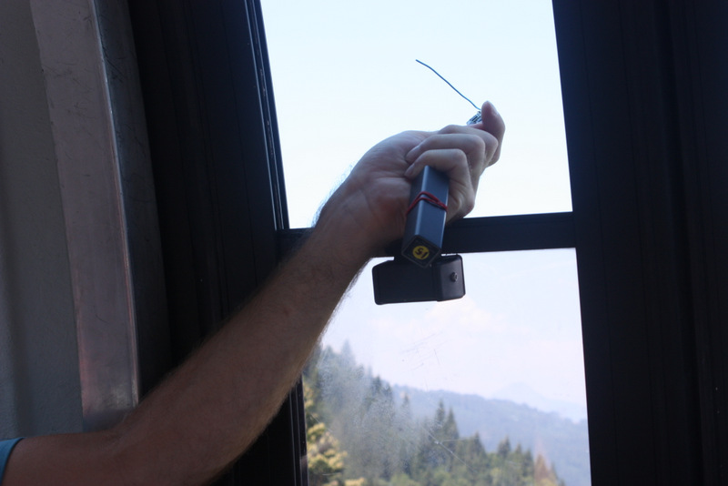
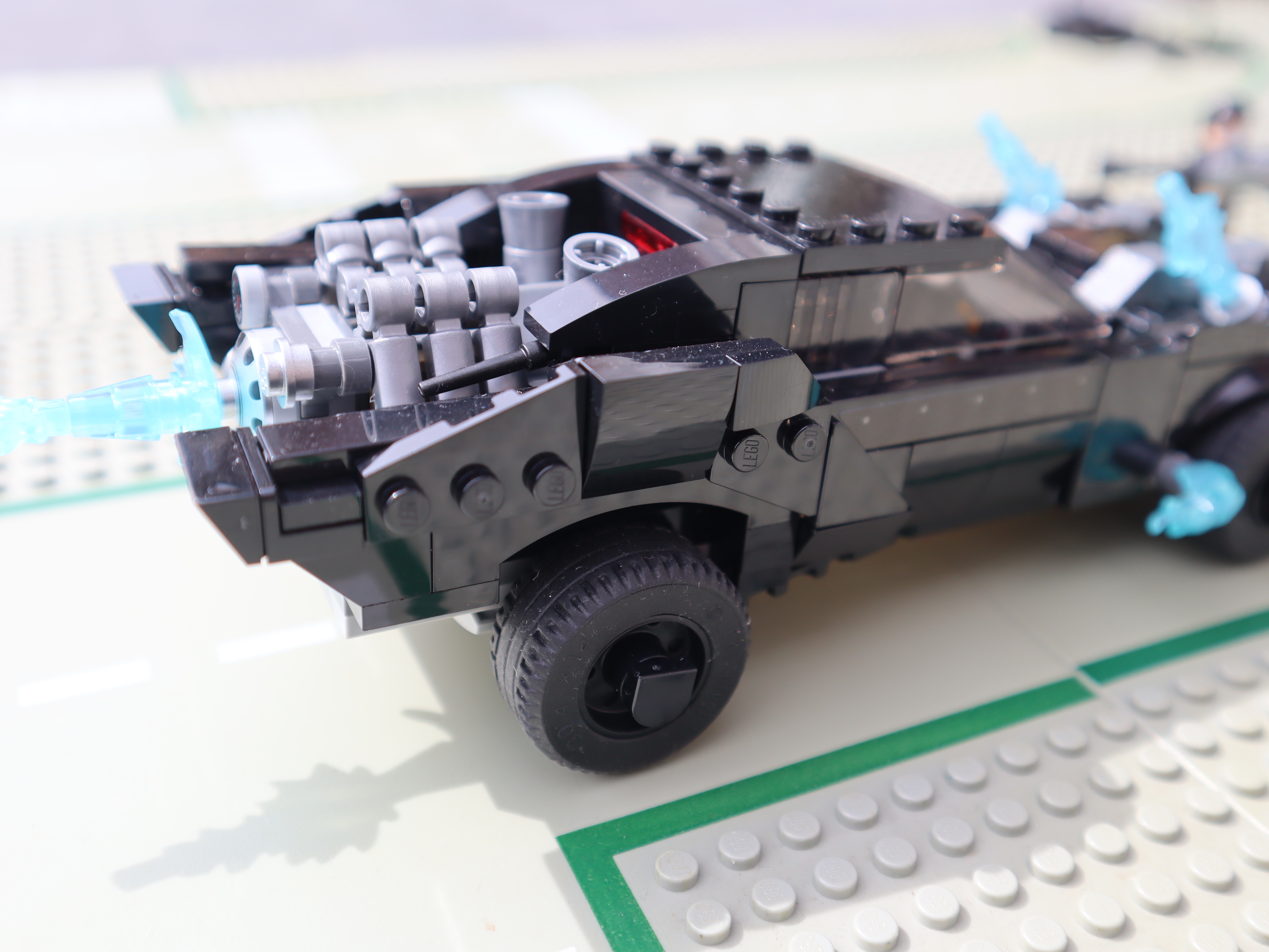
Weaponry come from 2 javelin missiles set in the front radiator which are launched by pressing the switches in the centre of the bonnet.


The Batman minifigure is decent, with a smug crooked smile expression which I like. The Penguin minifig doesn’t look much like a penguin to me, but as I said, I haven’t seen the movie yet. I’m also not sure how much of a “chase” it would be without the villain having a vehicle of his own, but I think I prefer the recent trend of just supplying a nemesis minifig with the Bat-vehicle, and not dreaming up a penguin-mobile (or whatever) which bumps up the cost of the set.  He does have a really big gun though!


Summary. This is a great set which is sturdy and offers good play-ability, as well as looking cool if you just want to display it. It’s a solid 8/10. 


Friday 19 July 2019

Apollo 11 Lego Display case with Raspberry Pi


When I'd finished building the Lego Apollo 11 set, i realised that such a special model needed to be on permanent display.


But if you've ever left some Lego out on a shelf for a few days you'll be aware that it attracts dust like jam attracts ants.

So I decided to make a simple perspex box to keep it under.

But then I started to think about adding some lights to the box... then I wanted to be able to control the lighting...so that would involve adding  a Raspberry Pi.... and things escalated from there.


The final build includes:

- A button to trigger audio samples from the moon landing, played on a Pimoroni SpeakerPhat.


- Neopixel sticks to illuminate the scene and provide mood lighting. Ther are attached to the Lego using 3D printed mountings.


The neopixels  also used to indicate the status of the Raspberry Pi Zero that runs the whole thing. For example they perform a  single LED Larson scan at startup.

- An image of the Earth etched onto the box


- 3 switches to 'program' different lighting moods and safely shutdown the Pi that controls everything. I liked the idea if being able to essentially alter the program by flipping switches, a bit like the Apollo guidance computer. I couldn't find any reasonably priced flat switches but might try to 3D print some paddles to add to these ones at a later date.


- 3 potentiometers (connected via an MCP3008 ADC)  to manually adjust the RGB values for the LEDs


The gubbins inside could do with some tidying up but should be robust enough (and there is plenty of space) - everything is either soldered or uses screw terminals.


 Here are some other images of the case


Sunday 16 September 2018

Using Desktop Raspbian with a second screen or projector

After various dalliances with Mint, Mate, Elementary and vanilla Ubuntu, we've decided to standardise on the Desktop version of Raspbian for the "club" laptops that we have available at CoderDojo Ham,

There's a couple of reasons for this. Firstly it installs easily and quickly, and runs well on old, low.  powered devices (most of our laptops are donated or re-furbished) . Secondly, it comes with loads of great educational software and editors installed be default, which saves time in preparing the machines for use.

An important part of our Dojo is the show-n-tell at the end, where the keen youngsters show off their amazing projects on the big screen. This is always hugely popular and we normally have a long queue of patient coders to get through.

One thong we hadn't thought about when selecting Desktop Raspbian as our operating system of choice was using the club machines with the AV desk and getting them to display on the Kingston University STEM centre's excellent big screens. The first time we connected the VGA cable to the port on one of the laptops, nothing appeared to happen, and none of the menu setting within Raspbian seemed to help. Obviously the look and feel of Raspbian is geared towards the Raspberry Pi, so using multiple displays is not a common configuration.

After some messing around we discovered that reboot the laptop allowed the projector to be detected, although the default setting seemed to be for 2 screens rather than having the second mirror the first.

This is OK, but rebooting takes up precious time (remember the big queue) and having two windows can be confusing for the youngsters.

So a bit a experimentation revealed a better, simpler command line solution.

  1. Connect the second display
  2. Open a Terminal Window 
  3. Type xrandr --auto


This should automatically detect the new output device and set-up mirroring.

Some other useful commands

xrandr --listmonitors 


(this lists all the detected monitors)

xrandr --output <laptop monitor name> --same-as <projector name> 

(this forces mirroring - you can also add in other parameters, for example if the aspect ratios of the two screens were very different).


Tuesday 21 August 2018

Bash wifi network switcher script for Raspberry Pi

I had a situation where I had a Raspberry Pi 3B+ in a location where there were two usable wifi networks in range, but neither were particularly reliable in terms of Internet access. The wifi networks themselves would stay up, but the ADSL connections used by the  routers would sometimes drop and stay down for a while (in the case of one, until someone rebooted it).

So I wanted the Pi to switch from one network to the other in the event of losing Internet connectivity.

So I wrote a bash script that can be run periodically by cron.


There are a number of ways to achieve this,  including using additional packages like nmcli, but I wanted something that should just work on a plain version of Raspbian.

I also decided to test it on older Pis without built-in wifi and using a doingle instead. I found that a few tweaks were required to get the script to work reliably. 

I also encountered one situation where the Pi under test ended up not connected to any wifi network at all. Annoyingly I have not been able to reproduce that outcome to identify what went wrong.

The script is set to switch between two networks, SSID1 and SSID1 - obviously you'll need to change these names to reflect your own environment. 

To use the script you'll need two different copies of your wpa_supplicant file - which contains the network name and pre-shared key (password) required to authenticate - , one for each SSID.  Give them sensible names like  wpa_supplicant_1.conf and  wpa_supplicant_2.conf.

The script logs to a file wifi.log - this can be useful for debugging. It also echoes to the terminal too, to make it easier to see what's going on when testing. If you don't want any of this, just remove or comment out the 'echo' lines. 

There's no reason that this shouldn't work on other Debian distros or more widely on Linux, but I have not tested it.

The script needs to be run on a Pi with sudo. If you want to schedule using cron, then type 

sudo crontab -e

and then add a line to run as frequently as you like. For example:

0 */2 * * * /home/pi/wifitest.sh

Don't forget to make the file executable

chmod +x /home/pi/wifitest.sh

Tuesday 14 August 2018

Testing Adafruit Feather M0 LoRa 900MHz in the Alps

One of my birthday presents this year was  two 900MHz Adafruit feather M0 LoRa 800MHz boards. I hadn't had a chance to try them out  but just before going on holiday I realised that our destination in the Alps might provide a nice testing ground (or mountain) so added them to my hold luggage.

I know that LoRa tech is capable of impressive line-of-sight distances when there are no obstructions, but as I hadn't had time to pack my HAB gear, I needed to find some other way of testing the range.

The Feather boards are a nice size and I was just using a length of wire as an antenna. Example client/server Arduino code from the Radiohead RFM0x library was good enough for my purposes. Each board would blink its LED when it received a packet so I could see if data was being exchanged.

For the tests, one board  stayed back at base in the chalet - shoved out the Velux window for maximum height.


It was very sunny and hot so I decided that the base Feather ought to have some shade.


The second board came along with me on my travels, powered by a battery pack.


Over a few days I took the Feather out with me, first of all just cycling around the town, then for a grander test, heading up the mountain in the Grand Massif tele-cabin.


On the ascent, I was surprised to not be picking up any packets, even though I had been able to get good reception if I wondered about in the car park at the bottom. Thinking that the cabin itself might be acting as a bit of a Faraday cage, I poked the Feather out the window, and immediately started seeing the blinkin' red LED.


The contours of the mountain meant that there was actually quite a lot of rock and trees in between the two boards right at the top of the tele-cabin, and despite some wandering around to try to get better reception, the LED stayed off until we'd trekked some way  further up the mountain.

Fortunately you can also get a chair lift even higher, so we continued  to ascend to 2100m (the chalet itself is at 700m).


At the top the signal was very strong and with binoculars we could actually see the chalet down in the valley.

I recorded the various locations using the GPS Waypoint app on my phone and then exported these via KML into Google Earth. Red markers are places where there was no reception, green are where packets could be received.


This allows me to calculate the straight line distance between the two boards - the maximum distance was 5.86km, 


Even on flat ground,  with trees and buildings in the way, I was still able to exchange packets at 2.60km, and after that point I rounded the edge of the opposite mountain which probably blocked any further data.


So I was very impressed with the boards. They'll certainly be up to relaying data from my new shed....


Thursday 28 September 2017

Pivarium: care for your reptiles with a Raspberry Pi

It's been a while since there’s been a new addition to the family and I’d forgotten how much preparation is involved. All the familiar concerns that I remembered from when the boys were born came flooding back: you need to make sure the new arrival is not too hot or cold, provide a safe environment that they can’t escape from, ensuring they’re safe at night...

Snakes, I've discovered, are a lot like children. Except easier to feed. 


Anyway, faced with such challenges there is only one response: make some stuff to help.

Of course when the boys were born, the Maker community wasn’t as well established and, Raspberry Pi, the core of many IoT projects had yet to be born itself. So this project gave me an opportunity make up for it now.  The Pivarium deals with the the main requirements mentioned above.

Monitoring the environment inside the vivarium.


Snakes are ectotherms - they have no internal means of regulating metabolic function and maintaining homeostasis. In cold weather, snakes tend to be sluggish as their metabolisms slow down, whereas in warm weather they tend to eat more and move more quickly.  So in captivity they need to have a temperature gradient available so that they can move to a cooler place when they get too hot and vice versa. The Kernels vivarium has a  thermostatically controlled ceramic heat lamp at one end but I wanted to monitor the temperature under it,  as well as at the opposite end where there is more ventilation. 
I opted for DS18B20 temperature sensors because they are cheap and reasonably water -and hopefully snake pee - resistant. I was too lazy to convert the ends of the leads to female jumper sockets so I just used screw terminals and a small breadboard. My excuse is that this will make it easier to replace a faulty sensor in future. 
DS18B20 (left) next to probe from thermostat at 'hot end'

ADS18B20 at 'cool end'

The humidity in the Pivarium is also important, especially when the snake is shedding its skin so I wanted to monitor that as well I opted for a DHT22 which can also record temperature as well and is more accurate than the cheaper DHT11.  Therefore I placed it in the centre of the vivarium, attached to the roof. This gives me a third temperature reading to provide a good overall idea of what the gradient is like in the vivarium.
DHT22 mounted on roof

While I was testing and The Kernel was settling in,  I used a Pi Touchscreen to display a dynamic plot of the temperature and humidity values in real time. This was produced using Jupyter Notebook and the Python Matplotlib library. 


Once I was happy that everything was working and reasonably stable removed the touchscreen and swapped the Pi 2 for a Zero W. I still wanted to keep a graphical record of the environment though, so I created a data bucket on InitialState and upload regularly the data to produce a nice dashboard that I can check from anywhere that I can get on the InterWebs. 


InitialState dashboard


For a local display, I dont really need graphs - just the headline readings are fine. I also didnt want something bright and flashy like an LED matrix so I opted for the excellent Pimoroni InkyPhat. This is perfect as I only need to update the values every 5 minutes or so - things dont change that rapidly in the Pivarium.  Although the InkyPhat is limited to three colours, thats fine.  I want to easily see if a temperature is outside the desirable range for that area of the Vivarium, in which case the value is displayed in red text, otherwise black. I also display the time so I can tell that the readings are current and that the Pi or Inkyphat hasn’t stuck or crashed. 


I want to easily see if a temperature is outside the desirable range for that area of the Vivarium, in which case the value is displayed in red text, otherwise black. I also display the time so I can tell that the readings are current and that the Pi or Inkyphat hasn’t stuck or crashed. 

Night Vision

The next task was to see what The Kernel was getting up to at night. At a later stage I might put a camera in the vivarium itself, but for now I’m happy to have a second Pi outside with a Pi Noir camera and some IR LEDs, all mounted in a Lego frame.   Reflection from the vivarium glass in minimal and I can easily position the whole thing to focus on a particular area (e.g the hot or cold hide, the water bowl etc). I didnt want to record all the time so I used Motion software to detect when activity was occurring and start recording then. 

Ive been able to capture some good footage of The Kernels nocturnal behaviour. My favourite so far has been this clip of him having a big drink and then burping.


Houdini

The final task was to prevent The Kernel from unexpectedly leaving his lovely home. Corn snakes are renowned escape artists and will find a way out through any small crack or opening. A common escape route is cased by the sliding vivarium doors not being closed properly and the patient and surprisingly strong guest levering their way out when nobody is looking. A simple remedy is to always fit the sliding vivarium lock and mark its position on the bar so that you know the doors are fully closed. However it is really easy to forget this or to not lock the doors immediately and then forget to do it later (especially when removing snake poo). So  I wanted to add some blinkin LEDs to provide an immediate visual indication that doors were not secure. 
I found some nice chunky contact switches (with a satisfying click). These have 3 spade-connector terminals, a different pair of which are connected together when the switch is closed or open.    I designed some 3D printable brackets to fit hold them and allow easy fixing to the side of the vivarium. I also added a hole and channel for a blinking LED.
I also 3D printed some handles to fit onto the existing glass squares that are used to slide the doors. These press against and close the contact switches: the advantage of 3D printing these was that I could precisely adjust the size so that the switch is only fully depressed when the door is completely closed. 


As usual, the Python gpiozero  library makes the code to control these switches embarrassingly easy, especially using source/values.


from gpiozero import Button,LED
leftside = Button(20)
leftside_led = LED(21)
leftside_led.source = leftside.values
rightside = Button(19)
rightside_led = LED(26)
rightside_led.source = rightside.values

You can see the complete Python code for the Pivarium here. The STL files for the various 3D printed files and the Jupyter Notebook file used in testing are also there. 

Wednesday 2 August 2017

Introducing your Pi-rsonal Trainer

Since starting a new job earlier in the year I've had to make a lot of  adjustments to my fitness schedule. One thing I really miss are the exercise classes I used to attend. I particularly miss the High Intensity Interval Training sessions which were a great way get a quick cardiovascular workout.

I'd been rolling my own version at home in the back garden for a few weeks and found that although these sessions worked reasonably well,  I missed the class instructor who used to call out the next exercises and provide motivational commentary. Keeping track of what exercise I've just done gets increasingly difficult the more tired I get.  I also found it annoying to have to check my watch for when to pause between exercises and re-setting a timer every 20 seconds is annoying.

Obviously it would be hard to simulate the enthusiasm of a trainer but the exercise choice and timings seemed like a straightforward thing to automate with a Raspberry Pi.


I wanted a visual and audible alerting mechanism and something that would be small enough to be readily portable and run from a standard power bank.

Here is the finished prototype: my Pi-rsonal Trainer.


BoM

Pi Zero running Raspbian Jessie-lite and with the ScrollPhat HD Python library installed.
Pimoroni ScrollPhat HD
Pimoroni Pico HAT Hacker
Buzzer
Two push buttons

Construction


1) Solder a standard male header onto the Pi Zero.
2) Solder on the Pico HAT Hacker, being careful not to let the solder wick too far up the pins.
3) Solder a small buzzer directly on to the Pico HAT Hacker between the holes for Ground and GPIO 18
4) Solder two buttons onto the Pico HAT Hacker, one between Ground and GPIO 9 and the other between a different Ground pin and GPIO 19.
5) Solder a female header on to the ScrollPhat HD and then mount this onto the Pi.


Operation

For my HIIT sessions I like to have 4 repetitions of 10 x 20s periods of exercise interspersed with 10 second rests.

Some simple Python code runs at startup-up. When the bigger button (on GPIO19) is pressed, the sequence begins with an on/off flash of all the LEDs on the ScrollPhat . An exercise is selected at random from a list and this choice is scrolled across the matrix for 5 seconds, followed by a 5 second countdown accompanied by beeps. Then there's another flash and the 20 second exercise period begins. The exercise being undertaken is constantly scrolled across the LED matrix until the last 5 seconds when there's another beeping countdown. Then there's a 10 second rest period during with the next exercise is scrolled. And repeat 10 times.

Then a 30 second break.

Then repeat all that 4 times!


The LEDs of the ScrollPhat HD are nice and bright, and visible in full sunshine. The beeps are annoyingly shrill so that I can hear them even though I'll normally be listening to music on my earbuds. This means I don't have to keep watching the LED display to now when the various intervals are finished.

The code is easily customisable if you want different exercises or want to alter the timings. You could just as easily program a Yoga session rather than a HIIT workout!